3.9 SECTION OR SECTIONAL VIEWS.
3.9.1 Sectional Views Shall Be in Accordance with ASME Y14.3M.
3.9.1.1 Sectional View Cutting Plane. A section or a sectional view is obtained by cutting away part of an object to shape and construction at the cutting plane. Sectional views shall not be taken from another sectional view.
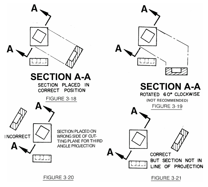
3.9.2 Placement of Sections. Sectional views are placed as closely as practicable behind the arrows showing the direction from which the view was taken. See FIGURE 3-18. When it is absolutely necessary to rotate a sectional view, the degree of rotation and direction are specified beneath the view. See FIGURE 3-19. Cutting planes for a single full section of a symmetrical part are not necessary, but when two or more sections are taken, all sections shall be identified. Sectional views shall be in line of projection, see FIGURE 3-20 and FIGURE 3-21, or otherwise identified if for some valid reason, (e.g. rotated, or separate sheet, etc.)
3.9.2.1 Sectional Views on Separate Sheet. Sectional views should appear on the same sheet as the subassembly, assembly, or detail drawings from which they are taken. When it is necessary to show sectional views on a separate sheet, view and cutting plane indications should be suitably cross-referenced by sheet and zone designations. When a sectional view appears on a different sheet than the sheet containing the cutting plane indication, the view will be oriented as it would appear if directly projected from the cutting plane and properly cross referenced.
3.9.3 Section and View Identification Letters. Section letters are always used in pairs, A-A, B-B, C-C, etc. Should a drawing require so many sections that the single letters of the alphabet are exhausted; further sections may be identified by the use of combinations of different letters such as AA-AA, AB-AB, AC-AC, etc. The letters I, O, Q, S, X and Z are not used as section letters. Once a letter or combination of letters is established on a released drawing, it is not reused for another SECTION, VIEW, or DETAIL on the same drawing.
![]()
3.9.4 Section Titles. The letters which identify a cutting plane are used as part of the section title, which is placed directly under the section view. The word "SECTION" is not abbreviated. See FIGURE 3-22.
![]()
Section Title
Figure 3-22
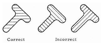
3.9.5 Angle of Section Lining. Section lining is generally constructed at an angle to the principal object lines of the sectional view, as shown in Figure 3-23, regardless of the position of the section on the drawing.
Angle of Section Lines
Figure 3-23
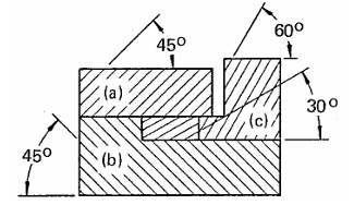
3.9.6 Section Lining or Cross-Sectioning. Sections lines are composed of uniformly spaced lines at an angle of 45 degrees to the base line of the section. On adjacent parts (a) and (b) in the figure below, the 45-degree lines are drawn in the opposite direction. On a third part, (c) adjacent to two other parts, the section lining shall be drawn at an angle of 30 or 60 degrees. See FIGURE 3-24. Where the 45-degree section lining is parallel or nearly parallel with the outline of the object, another angle is chosen.
Section Lines of Adjacent Parts
Figure 3-24
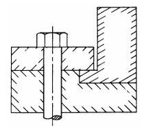
3.9.6.1 Section Lining for Clarity. In addition to showing the shape and construction, sectional views may also be used to distinguish the individual components of an assembly or subassembly. This is accomplished by drawing sectional conventions on the exposed surfaces of the sectional view. Sectioning conventions do not cross dimensions or obscure other conventions on drawings. Sectioning conventions may be shown along the borders of the part only when clarity is not sacrificed. See FIGURE 3-25.
Sectioning Adjacent Parts
Figure 3-25
3.9.6.2 Section Through Welds. If a cutting plane passes through two or more parts that are being permanently assembled by welding, brazing, etc., each detail part is individually cross-sectioned. When a group of permanently assembled parts is sectioned on its next assembly(s), it is cross sectioned as one part.
3.9.7 Scale of Sections. Sections should be drawn to the same scale as the views from which they are taken; if it is necessary to employ a different scale, it is specified directly below the section title as in PARAGRAPH 3.5.2 and FIGURE 3-5.
3.9.8 Types of Sections and Sectional Views.
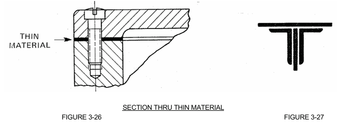
3.9.8.1 Thin Sections. Sections of sheet metal, packing, gaskets, etc., which are too thin for section lining, may be shown solid. See FIGURE 3-26. Where two or more thicknesses are shown, space conducive to microfilming should be left between them. See FIGURE 3-27.
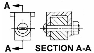
3.9.8.2 Unlined Sections. Shafts, nuts, bolts, rods, rivets, keys, pins, and similar parts, whose axes lie in the cutting plane, are typically not cross-sectioned. See FIGURE 3-28.
Unlined Sections
Figure 3-28
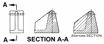
3.9.8.3 Sections Through Ribs, Webs, Etc. When the cutting plane passes through a rib, web, or similar element, section lines may be omitted from these parts. An acceptable alternate method of representation is to portray the line of intersection of the element (rib, web, etc.) with a hidden line. In cross sectioning the element, every other section line is omitted to accent the division of the element and the body of the part. See FIGURE 3-29.
Section Thru Ribs
Figure 3-29
3.9.8.4 Full Sections. A full section is a view which is obtained when the cutting plane extends entirely across the object. See FIGURE 3-30. Cutting plane lines may be omitted if the location of the cutting plane is obvious.

Full Sectional View
Figure 3-30


