3.6 LETTERING.
Note: CAD software and the font styles and font sets therein should be formatted and set up so the following requirements are achieved. In general, the output from CAD systems and the quality of lettering far exceeds what was possible on manually prepared drawings.
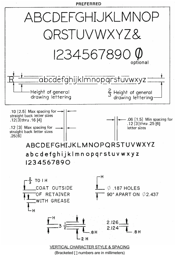
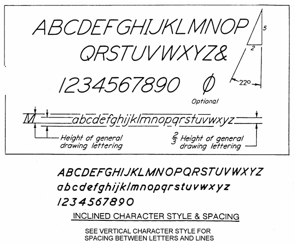
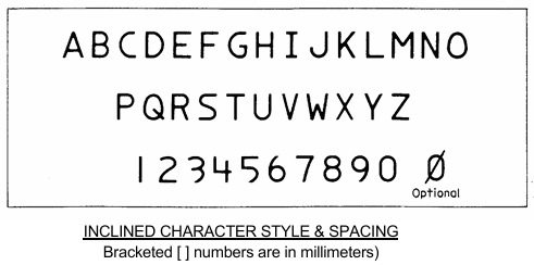
3.6.1 Lettering. (except SECTION, DETAIL or VIEW "Letters") Lettering shall be single stroke upper case, commercial gothic; however, for special design requirements (i.e., name plates, connector pin, etc.), lower case lettering may be used. Inclined or vertical (Preferred) lettering may be used but only one type shall appear on a single drawing. See FIGURES 3-7a, 3-7b and 3-7c for lettering styles.
3.6.2 Letter Application. Freehand lettering, typewriter, or the use of mechanical lettering devices such as templates and lettering machines may be used. Whatever method used all characters, in general, are to conform to gothic style and must be legible in full or reduced size copy using any accepted method of reproduction.
3.6.3 Letters and Numerals with Similarities. Alpha and numeric characters that are similar shall be readily distinguishable to the reader as follows:

Figure 3-7a

Figure 3-7b

Figure 3-7c
3.6.4 Letter Spacing. Letter spacing should be spaced as evenly and consistently as possible. Normally, the space between words and between lines should be greater than the height of one letter minimum. Lettering shall be such that microfilm blow back and reproductions of the drawing shall not show evidence of filled-in loops or leaching of character to character.
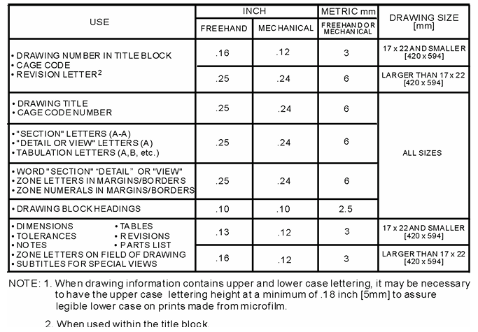
3.6.5 Lettering Size. All lettering must meet microfilm reproduction requirements. The letter sizes listed in TABLE 3-2 provide those minimum heights.

Recommended Minimum Letter Heights
Table 3-2
3.6.6 Letters and Numerals Position. Letters and numerals shall be printed parallel to the bottom of the drawing, regardless of the position of dimension lines. The only exception is given in ASME Y14.5M-1994, which allows certain dimension and tolerance values to be oriented such that they may be read from the right side of the drawing when using the baseline style of rectangular coordinate dimensioning.


