3.1 SCOPE.
3.1.1 Purpose. This section defines various drafting practices such as drawing scale, lettering, line work, sectioning, and projection, and descriptive geometry applicable to making new engineering drawings and their subsequent revisions. Note: Some material from this section has been relocated to Appendix A1 “Past Practices – Manual Drafting Techniques.” The material may still be pertinent for those companies still producing drawings manually and/or having to revise manually prepared existing drawings, but most of industry has adopted CAD as the preferred medium for generating drawings. Thus, some of this content may be considered as outdated by some readers. To allay this concern we moved the material to the aforementioned Appendix. Some content that is mostly pertinent to manual drawing preparation has been retained in this SECTION as it also applies to CAD-generated drawings.
3.2 APPLICABLE DOCUMENTS. Note: DoD Policy Memo 05-3 “Elimination of Waivers to Cite Military Specifications and Standards in Solicitation and Contracts” has eliminated the need for waivers to use MIL-SPECS and MIL-STDS on DoD contracts. (See PREFACE 1, Section 2)
3.3 DEFINITIONS. (Alphabetically Listed)
3.3.1 Engineering Drawing. An engineering drawing is an engineering document or digital data file(s) that discloses by means of pictorial or textual presentations, or combinations of both, directly or by reference, the physical and functional end product engineering requirements of an item.
3.3.1.1 Dimensioned Drawing. A drawing depicting a design with the size given, as applicable, by means of dimensions.
3.3.1.2 Un dimensioned Drawing. A drawing depicted to a precise scale on environmental stable material and used for printed circuits and loft line information and fabrication of templates, patterns, or printed circuits.
3.3.1.3 Digital Data (Digital Drawing). Engineering drawings prepared by other than manual means (such as computer-generated drawings) shall provide all of the information required by the particular drawing type or level of design disclosure. Minor variations from the requirements as specified herein to accommodate document preparation are acceptable as long as these variations meet the requirements relative to the information contents.
3.3.2 Enlargement Scale. A scale where the ratio is larger than 1 to 1 and the object presentation increases in size as the ratio increases.
3.3.3 Full Size. A scale with a ratio of 1 to 1 or actual size.
3.3.4 Layout Drawing. A drawing clearly showing the shapes, sizes, location, clearances, and materials of a design and its adjacent parts. Layouts are used to convey information to customers, vendors, and as a master drawing from which "production" drawings are prepared. Layout drawings are not released for the manufacture of parts.
3.3.5 Production Drawing. An engineering drawing that discloses the physical and functional engineering end product requirements for parts, assemblies and installations required for the manufacture or assembly of an experimental or production model end item. They are released, controlled and normally required for customer submittal.
3.3.6 Reduction Scale. A scale where the ratio is smaller than 1 to 1 and the object presentation decreases in size as the ratio decreases.
3.3.7 Scale. The ratio of the size of an object represented on a drawing compared to the actual size of the object.
3.4 GENERAL PRINCIPLES OF PRESENTATION.
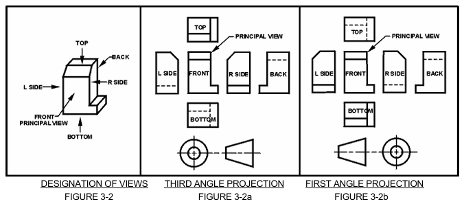
3.4.1 Orthographic Projection. Orthographic projection methods shall be applied to technical engineering drawings for the purpose of uniformity. All example drawings and figures portrayed in this manual will be presented using the "third angle projection method". This policy is generally adopted in the U.S. while the "first angle projection method" is used internationally (ISO).
3.4.2 Method of Identifying the Relative Position of Drawing Views. To clarify any confusion regarding the arrangement of views (this manual shows both inch [U.S.] and metric [international] treatments), the following symbols will be added to drawings as necessary to verify the angle projection method that is portrayed. See FIGURE 3-1.

Angle Projection Method
Figure 3-1
3.4.3 Third Angle Projection Method. This method is preferred and used in the U.S. See FIGURE 3-2a. For interpretation of this method See FIGURE 3-2.
3.4.4 First Angle Projection Method. Countries using international (ISO) standards prefer this method. See FIGURE 3-2b. For interpretation of this method See FIGURE 3-2.
3.4.5 Use of Projection Symbol. The appearance of the third angle projection symbol in the vicinity of the title block as described in Section M4 is as follows:
- U.S. drawings using inch dimensioning - Not required.
- U.S. drawings using metric dimensioning - Mandatory use.
- INTERNATIONAL (ISO users) using metric dimensioning - Not required.
3.4.6 Microfilming Requirements for Drawings in Accordance with MIL-M-9868, Excluding Layouts. Major drawing defects resulting in rejected microfilm are: numbers or characters too light, not clear, or illegible, discontinuous or light lines, and foreign material or markings in drawing area. Adherence to the following guidelines will assist in keeping microfilm rejections to a minimum. MIL-M-9868 is inactive for new application after 1/6/95: Use JEDMICS. See PARAGRAPH 3.4.7.
3.4.6.1 New Drawings. Drawing lines and lettering shall meet the legibility and reproducibility requirements of MIL-PRF-5480 and shall be in accordance with ASME Y14.2M and the following:
- Do not show unnecessary views.
- When possible, place views, sections and Parts List columns between the micro film match lines. See FIGURE 3-3.
- Use standard size drawing formats (See SECTION 6) with microfilm arrow marks.
- Lines and characters shall have even density in accordance with ASME Y14.2M.
- Avoid use of parentheses in notes, field call outs or parts lists.
- Drawings made with photographs will not meet microfilm requirements and must not specifically authorized by contract.
- Decimal points must be uniform, dense and large enough to be of microfilm quality.
3.4.6.2 Revised Drawings. Same as for "new drawings" plus the following:
- Letters, numbers, and line weights shall be consistent with the original drawing preparation.
- Conform to original style of lettering.
Note: The bullet letters missing the sequence above have been moved to Non-Mandatory Appendix A at the end of the DRM. See PARAGRAPH 3.4.6.1 in Appendix A for-drawing rules specific to manually prepared (non-CAD) drawings.
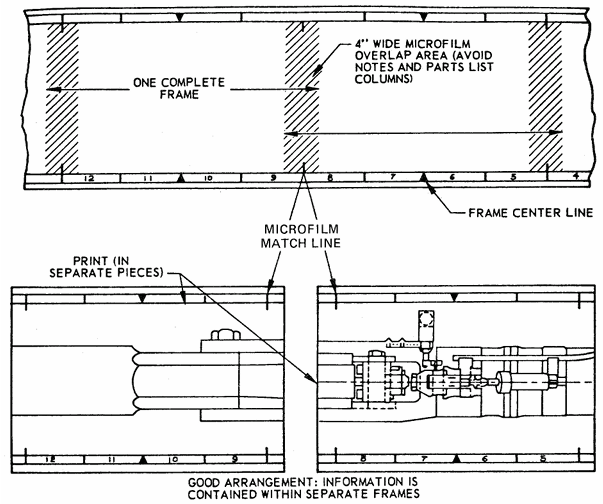
Placing of Views Between Microfilm Match Lines
Figure 3-3
3.4.6.3 Computer-Aided Design (CAD) Drawings. The use of digital data files in preparing drawings is acceptable provided:
- Line conventions and letters may vary for digital data file prepared drawings provided that applicable legibility requirements are met.
- Drawing maintenance requirements and the requirements of this Drawing Requirements Manual (DRM) can be met.
- Microfilming requirements per MIL-M-9868 (Inactive for new application after 1/6/95) can be met. Use JEDMICS. See PARAGRAPH 3.4.7.
- Digital data files are prepared in accordance with the Joint Engineering Data Management Information and Control System (JEDMICS) for storing, retrieving, controlling, managing and distributing engineering data in standard digital format throughout DoD and Industry. Engineering data stored, controlled and distributed by JEDMICS supports the following:
- Manufacture, installation, operation and maintenance of equipment.
- Receipt of engineering data from original equipment manufacturers.
- Re-engineering parts to different specifications.
- Preparing bid sets for spare and repair parts acquisition and replenishment.
3.4.7 Digital Data Delivery Per JEDMICS. Digital data is the preferred delivery method for data. If this option is selected either by option or invoked by contract, it is imperative that an electronic format is selected that can be received, stored, retrieved and used by Government and Industry customers. (Ref: MIL-DTL-31000)
3.4.8 Axonometric (Isometric And Pictorial) Views. Isometric, pictorial, and other views are permitted on drawings as required. Such views are easy to create using 3D CAD software. Refer to PARAGRAPHS 26.1.3 and 26.5.5 in SECTION 26 and the remainder of SECTION 26 for more information.
3.5 SCALE OF DRAWING.
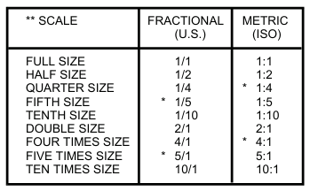
3.5.1 Scale Selection. Wherever possible, drawings should show an object or assembly to full scale, or larger where items or features are too small to see clearly if depicted at full scale. When not practical, drawings may be prepared to a reduced scale. See TABLE 3-1.
* Non-Preferred
** If there is a need for larger or smaller scale than those shown in the Table, it is recommended that the scale be derived by multiplying the whole number by powers of 10. Intermediate scales may be chosen when necessary.
Note: 2D and 3D CAD models should always be modeled at full scale. This excludes CAD files of diagrammatic drawings such as schematics and logic diagrams.
Preferred Drawing Scales
Table 3-1
3.5.2 Scale Indication. The primary scale of the overall drawing presentation shall be as a ratio and placed in the Drawing Scale Block located within the Title Block. See FIGURE 3-4.
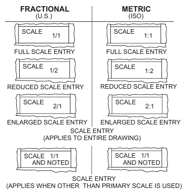
Scale Entry
Figure 3-4
3.5.3 Scale Indication Other Than Primary. Scales that either enlarge or reduce the object from the primary scale used on the drawing shall be identified and entered directly below the DETAIL, VIEW or SECTION extracted from the object. See FIGURE 3-5.
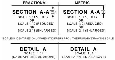
Sectional and Extracted Scale Identification
Figure 3-5
Note: The parenthetic comments shown in FIGURE 3-5 such as “(FULL)” or “(REDUCED)” is not required on the drawing.
3.5.4 Scale of Reproduced Print. The scale of the reproduced original drawing may differ from the original drawing as a result of the techniques, hardware, and software used to reduce or enlarge the drawing.
3.5.5 Change in Dimension. Drawings are drawn to scale within .03 inches. When dimensional changes are made on released drawings, and it is not practical to change the detail to agree with the new dimension, the dimension is underscored with a straight thick line to indicate the out-of-scale condition. See FIGURE 3-6. Care must be taken that if this action is taken on an older drawing, other out-of-scale dimensions shall be changed from the previous wavy line practice to the current straight thick line practice. Where the product definition is on an interactive computer graphics system the scale of the feature and dimension shall be maintained.
Note: This practice primarily applies to manually prepared drawings. Drawings prepared using CAD software and printing equipment (e.g. laser printers) should be more accurate than is described above.

Out-of-Scale Condition
Figure 3-6
3.5.6 Reduced Scale Drawings. Drawings may be made for large parts whose major view may be clearly shown at a smaller scale to reduce the size of the drawing format. These drawings may contain appropriately labeled larger size views or sections of complicated portions if necessary for clarity. See FIGURE 3-5.
3.5.7 Enlarged Scale Drawings. Drawings of exceptionally small parts or views may be drawn to an enlarged scale for clarity. See FIGURE 3-5.
3.5.8 No Scale Drawings. Certain drawings or figures, such as wiring and schematic diagram drawings cannot be drawn to a specific scale. On such drawings, the scale block shall read "NONE".
3.6 LETTERING.
Note: CAD software and the font styles and font sets therein should be formatted and set up so the following requirements are achieved. In general, the output from CAD systems and the quality of lettering far exceeds what was possible on manually prepared drawings.
3.6.1 Lettering. (except SECTION, DETAIL or VIEW "Letters") Lettering shall be single stroke upper case, commercial gothic; however, for special design requirements (i.e., name plates, connector pin, etc.), lower case lettering may be used. Inclined or vertical (Preferred) lettering may be used but only one type shall appear on a single drawing. See FIGURES 3-7a, 3-7b and 3-7c for lettering styles.
3.6.2 Letter Application. Freehand lettering, typewriter, or the use of mechanical lettering devices such as templates and lettering machines may be used. Whatever method used all characters, in general, are to conform to gothic style and must be legible in full or reduced size copy using any accepted method of reproduction.
3.6.3 Letters and Numerals with Similarities. Alpha and numeric characters that are similar shall be readily distinguishable to the reader as follows:
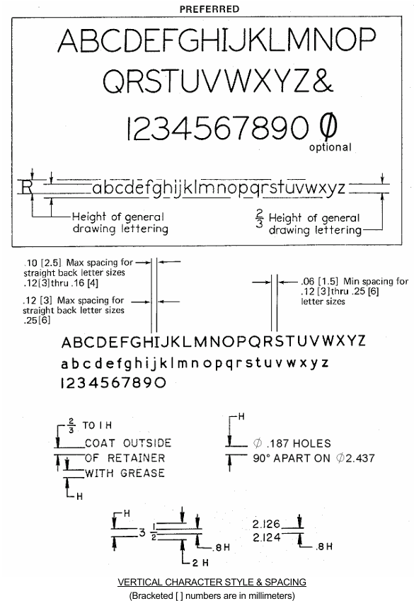
Figure 3-7a
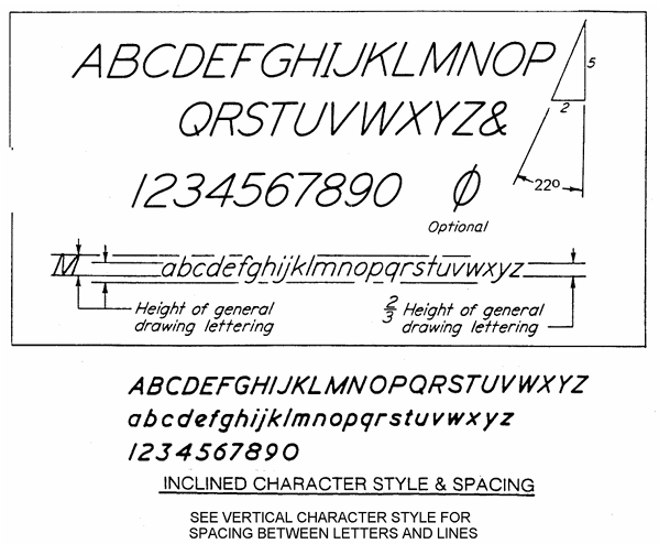
Figure 3-7b
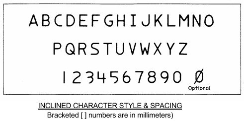
Figure 3-7c
3.6.4 Letter Spacing. Letter spacing should be spaced as evenly and consistently as possible. Normally, the space between words and between lines should be greater than the height of one letter minimum. Lettering shall be such that microfilm blow back and reproductions of the drawing shall not show evidence of filled-in loops or leaching of character to character.
3.6.5 Lettering Size. All lettering must meet microfilm reproduction requirements. The letter sizes listed in TABLE 3-2 provide those minimum heights.
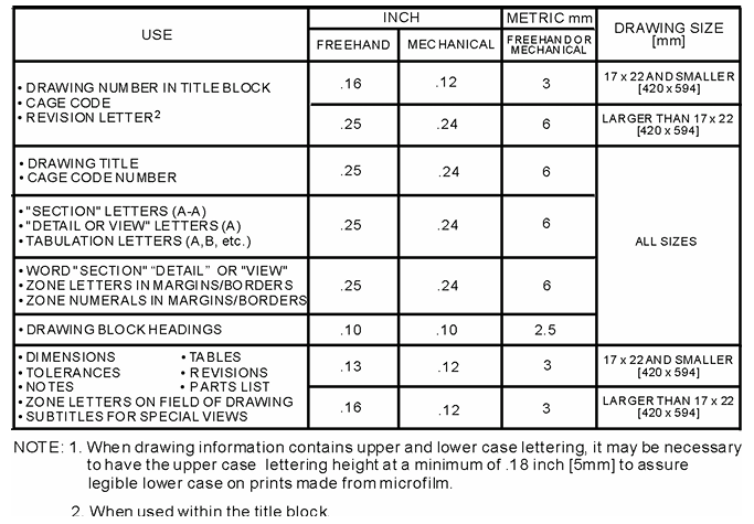
Recommended Minimum Letter Heights
Table 3-2
3.6.6 Letters and Numerals Position. Letters and numerals shall be printed parallel to the bottom of the drawing, regardless of the position of dimension lines. The only exception is given in ASME Y14.5M-1994, which allows certain dimension and tolerance values to be oriented such that they may be read from the right side of the drawing when using the baseline style of rectangular coordinate dimensioning.
3.7 TYPES OF LINES
3.7.1 Line Quality. All lines shall be opaque, and each type of line shall have uniform width, using the line characteristics recommended in TABLE 3-3, except on diagrammatic drawings. All lines shall satisfy the requirements for microfilming.
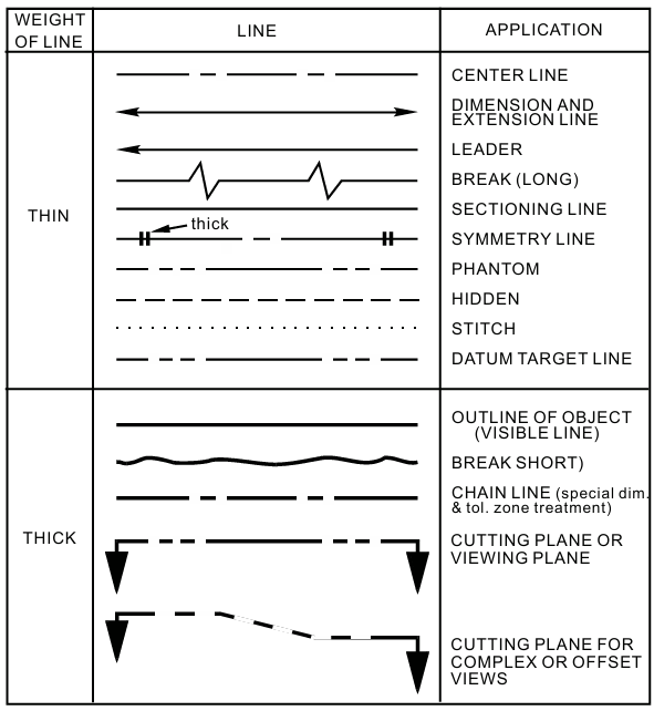
Types of Lines
Table 3-3
3.7.2 Dimension Lines. Dimension lines shall terminate in arrowheads and should be unbroken, except for the insertion of the dimension value and related information. When dimensioning radii, it is permissible to break the dimension line if true center of the radius falls off the drawing into another view or interferes with the logical dimensioning procedure. See TABLE 3-3 and FIGURE 3-8.
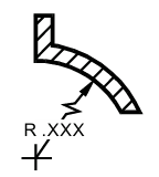
Broken Dimension Line
Figure 3-8
3.7.3 Leader Lines. Leader lines are used to indicate a feature, a part, a portion of a feature, or other annotation to which a dimension, note, or other reference applies. Leader lines are extended at a constant angle. Leader lines are not curved. See FIGURE 3-11. The end of the leader pointing toward the indicated feature shall terminate as follows (See TABLE 3-3 and FIGURE 3-9.)
- A leader that terminates at a line shall terminate in an arrowhead, except as shown in c. below.
- A leader that terminates within the outline of an object shall terminate in a dot.
- A leader that terminates at a dimension line as shown in c. below shall terminate without a dot or arrowhead.

Leader Lines
Figure 3-9
3.7.3.1 Arrowheads. Arrowheads are drawn as shown in FIGURE 3-10.
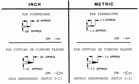
Arrowheads
Figure 3-10
3.7.3.2 Leader Lines Used with Notes. Leaders terminate at the lettering end with a line approximately .125 inch [3.18 millimeter] long, parallel to the lettering of the note and are extended at a constant angle to the part or portion affected by the note.
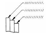
Termination of Leader Lines
Figure 3-11
3.7.3.3 Leader Lines Used with a Circular Area, Shaft, or Hole. The leader line from a dimension and/or local note to a circular area, shaft, or hole shall be directed toward the center of the circle representing the shaft, hole or area, with the arrowhead terminating at the edge of the circle. See FIGURE 3-12.
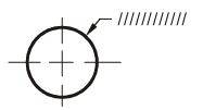
Leader Line Direction
Figure 3-12
3.7.3.4 Leader Lines That Cross Dimension Lines. Leader lines should not cross dimension or other leader extension lines. When it is unavoidable that a leader crosses a dimension line, the leader line or dimension line is not broken at the point of intersection.
3.7.4 Break Lines. Short breaks shall be indicated by solid freeform lines; long breaks shall be indicated by full ruled lines with zig zags. See TABLE 3-3 and FIGURE 3-13.

Break Lines
Figure 3-13
3.7.4.1 Break-Out Methods. Shafts, rods, tubes, etc., which have a portion of their length broken out, shall indicate the ends of the break as in FIGURE 3-14.
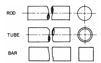
Breaklines
Figure 3-14
3.7.5 Center Lines. Center lines are shown in pertinent views of holes, round shapes on detail drawings, on assembly drawings to indicate the center of features, or to indicate the travel of a center. See TABLE 3-3 and FIGURE 3-15. Center lines may cross without voids. See FIGURE 3-14. Very short center lines may be unbroken if there is no confusion with other lines. (Note: Center lines are not required on annotated models.)
3.7.6 Phantom Lines. Phantom lines are used to indicate an alternate position, repeated detail, or the interfacing position of an absent part. They shall be composed by a series of one long and two short dashes evenly spaced with a long dash at each end. See TABLE 3.3 and FIGURES 3.15, 3.16 and 3.17.
3.7.7 Section Lining. Section lining shall be used to indicate the exposed surface of an object in a cross-sectional view. See TABLE 3-3 and FIGURE 3-15.
3.7.8 Extension Lines. Extension lines shall be used to indicate the extent of a dimension or an extension from a surface. They shall not touch the object outline. See TABLE 3-3 and FIGURE 3-15.
3.7.9 Datum Target Lines. Datum target lines are used to establish datum target lines or the boundary of datum target areas, and consist of one long dash and two short dashes evenly spaced, per TABLE 3-3. See SECTION 5 for the use of datum targets. Datum target lines are the same as Phantom lines.
3.7.10 Hidden Lines. Hidden lines are used to represent features that are not directly visible in a particular view. Hidden lines should be used when required for clarity and shall consist of short evenly spaced dashes. They should begin with a dash in contact with the line from which they start, except when such a dash would form a continuation of a collinear object line. Dashes should touch at corners, and arcs should start with dashes on the tangent points. See TABLE 3-3 and FIGURE 3-15.
3.7.10.1 Hidden Surfaces Intersect. If possible, when two or more hidden surfaces intersect, a dash in one line should cross a dash in the other line.
3.7.11 Cutting Plane and Viewing Lines. When it is necessary to indicate where a section is taken, a cutting plane line is used. Section letters are placed in front of the directional arrowheads, except for alternate viewing plane in which case they are placed in back of directional arrowheads. See TABLE 3-3 and FIGURE 3-15.
3.7.12 Object Lines (Outline Or Visible Outline). Object lines shall be used for all lines on the drawing representing the visible outlines of the object. See TABLE 3-3 and FIGURE 3-15.
3.7.13 Chain Lines. Chain lines are used to indicate a limited length or area receiving additional treatment within limits specified on the drawing. See FIGURE 3-15. Chain lines are also used to indicate a projected tolerance zone. Chain lines consist of appropriate length lines and short dashes. See TABLE 3-3.
3.7.14 Stitch Lines. Stitch lines are used to indicate a sewing or stitching process and are shown as dots approximately .01 inch [0.3mm] in diameter and .01 inch [0.3mm] apart. Short dashes may be used over extended lengths. See TABLE 3-3.
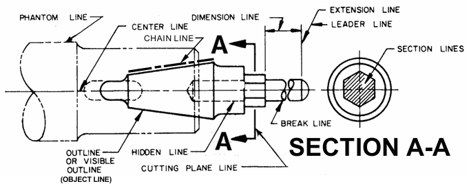
Line Conventions
Figure 3-15
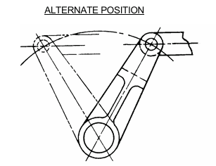
Alternate Position
Figure 3-16
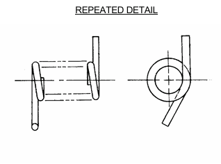
Repeated Detail
Figure 3-17
3.8 DRAFTING SYMBOLS
3.8.1 Drafting Symbol Definitions. Each drafting symbol shall be defined in a note or legend on the drawing or by reference to an approved source. Symbols depicted in this Manual are listed as follows:
See SECTION 6 for ZONE CROSS REFERENCE symbols.
See SECTION 9 for USE & SIZE OF FLAGNOTE (Delta) symbols.
See SECTION 5 for DIMENSIONING AND TOLERANCING AND GEOMETRIC DIMENSIONING AND TOLERANCING symbols.
See SECTION 13 for SURFACE TEXTURE symbols.
See SECTION 14 for WELDING symbols.
See SECTION 18 for ARCHITECTURAL symbols.
See SECTION 22 for ELECTRICAL and ELECTRONIC symbols.
3.8.2 Graphic Symbols, Designations, Letter Symbols and Abbreviations. (Listed Alphabetically) Graphic symbols, designations, letter symbols and abbreviations used on engineering drawings shall be in accordance with the standards indicated. Whenever any of the above is not covered by approved standards, they may be used provided they are explained on each drawing or referenced to another document. The referenced document for non-standard symbols shall be furnished with the engineering drawings.
3.8.2.1 Flow Chart Symbols and Their Used in Micrographics. AIIM MS04.
3.8.2.2 Graphic Symbols for Aircraft Hydraulic and Pneumatic Systems. SAE AS1290.
3.8.2.3 Graphic Symbols for Electrical and Electronics Diagrams. IEEE STD 315 & Suppl IEEE STD 315a.
3.8.2.4 Graphic Symbols for Fluid Power Diagrams. ASME Y32.10 (INACTIVE).
3.8.2.5 Graphic Symbols for Logic Functions. IEEE STD 91 & Supplement IEEE STD 91a.
3.8.2.6 Graphic Symbols for Plumbing Fixtures Used in Architecture & Building Construction. ANSI Y32.4 (INACTIVE).
3.8.2.7 Letter Symbols. ASME Y10.3M (INACTIVE), IEEE STD 260.1 and IEEE STD 280.
3.8.2.8 Logic Circuit Diagrams. IEEE STD 991.
3.8.2.9 Mathematical Signs and Symbols. IEEE STD 260.3.
3.8.2.10 Mechanical Symbols. MIL-STD-17/1 (INACTIVE), ASTM F 856, ASTM F 1000, or ASME Y32.2.6 (INACTIVE) as applicable.
3.8.2.11 Mechanical Symbols for Aerospace craft and Spacecraft Diagrams. MIL-STD-17/2 (INACTIVE).
3.8.2.12 Nondestructive Testing Symbols. AWS A2.4.
3.8.2.13 Printed Board Description in Digital Form. IPC-D-350 or MIL-STD-28000.
3.8.2.14 Printed Wiring Drawings. IPC-2221A, IPC-2222, MIL-STD-2118 and IPC-T-50, as applicable.
3.8.2.15 Reference Designations for Electrical and Electronics Parts and Equipment. IEEE STD 200, IEEE STD 315 and Supplement IEEE STD 315a.
3.8.2.16 Ship Structural Symbols. MIL-STD-25.
3.8.2.17 Welding Symbols. ANSI/AWS A2.4 Together with Terms and Definitions AWS A3.0.
3.9 SECTION OR SECTIONAL VIEWS.
3.9.1 Sectional Views Shall Be in Accordance with ASME Y14.3M.
3.9.1.1 Sectional View Cutting Plane. A section or a sectional view is obtained by cutting away part of an object to shape and construction at the cutting plane. Sectional views shall not be taken from another sectional view.
3.9.2 Placement of Sections. Sectional views are placed as closely as practicable behind the arrows showing the direction from which the view was taken. See FIGURE 3-18. When it is absolutely necessary to rotate a sectional view, the degree of rotation and direction are specified beneath the view. See FIGURE 3-19. Cutting planes for a single full section of a symmetrical part are not necessary, but when two or more sections are taken, all sections shall be identified. Sectional views shall be in line of projection, see FIGURE 3-20 and FIGURE 3-21, or otherwise identified if for some valid reason, (e.g. rotated, or separate sheet, etc.)
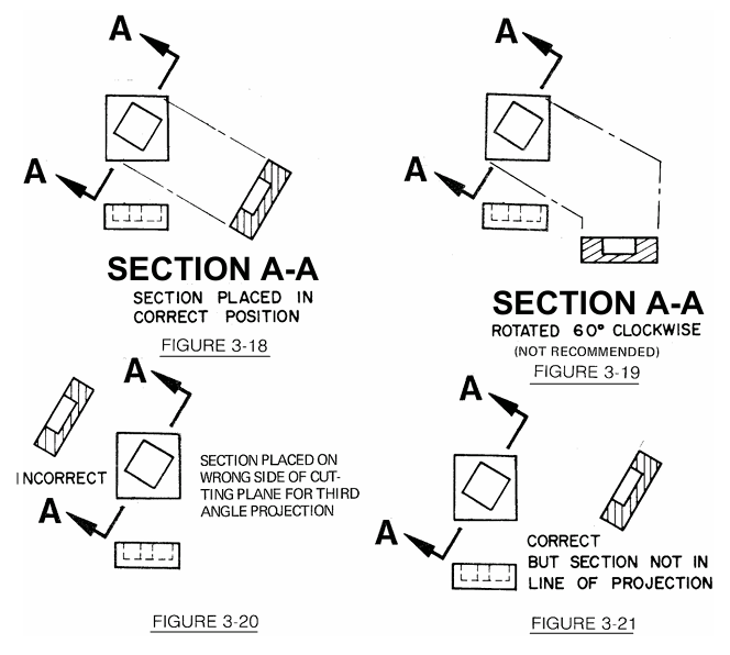
3.9.2.1 Sectional Views on Separate Sheet. Sectional views should appear on the same sheet as the subassembly, assembly, or detail drawings from which they are taken. When it is necessary to show sectional views on a separate sheet, view and cutting plane indications should be suitably cross-referenced by sheet and zone designations. When a sectional view appears on a different sheet than the sheet containing the cutting plane indication, the view will be oriented as it would appear if directly projected from the cutting plane and properly cross referenced.
3.9.3 Section and View Identification Letters. Section letters are always used in pairs, A-A, B-B, C-C, etc. Should a drawing require so many sections that the single letters of the alphabet are exhausted; further sections may be identified by the use of combinations of different letters such as AA-AA, AB-AB, AC-AC, etc. The letters I, O, Q, S, X and Z are not used as section letters. Once a letter or combination of letters is established on a released drawing, it is not reused for another SECTION, VIEW, or DETAIL on the same drawing.
![]()
3.9.4 Section Titles. The letters which identify a cutting plane are used as part of the section title, which is placed directly under the section view. The word "SECTION" is not abbreviated. See FIGURE 3-22.
![]()
Section Title
Figure 3-22
3.9.5 Angle of Section Lining. Section lining is generally constructed at an angle to the principal object lines of the sectional view, as shown in Figure 3-23, regardless of the position of the section on the drawing.
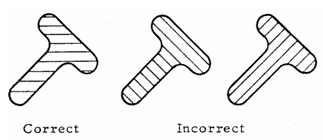
Angle of Section Lines
Figure 3-23
3.9.6 Section Lining or Cross-Sectioning. Sections lines are composed of uniformly spaced lines at an angle of 45 degrees to the base line of the section. On adjacent parts (a) and (b) in the figure below, the 45-degree lines are drawn in the opposite direction. On a third part, (c) adjacent to two other parts, the section lining shall be drawn at an angle of 30 or 60 degrees. See FIGURE 3-24. Where the 45-degree section lining is parallel or nearly parallel with the outline of the object, another angle is chosen.
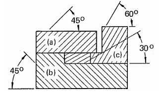
Section Lines of Adjacent Parts
Figure 3-24
3.9.6.1 Section Lining for Clarity. In addition to showing the shape and construction, sectional views may also be used to distinguish the individual components of an assembly or subassembly. This is accomplished by drawing sectional conventions on the exposed surfaces of the sectional view. Sectioning conventions do not cross dimensions or obscure other conventions on drawings. Sectioning conventions may be shown along the borders of the part only when clarity is not sacrificed. See FIGURE 3-25.
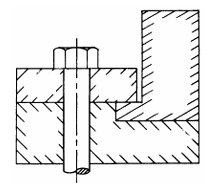
Sectioning Adjacent Parts
Figure 3-25
3.9.6.2 Section Through Welds. If a cutting plane passes through two or more parts that are being permanently assembled by welding, brazing, etc., each detail part is individually cross-sectioned. When a group of permanently assembled parts is sectioned on its next assembly(s), it is cross sectioned as one part.
3.9.7 Scale of Sections. Sections should be drawn to the same scale as the views from which they are taken; if it is necessary to employ a different scale, it is specified directly below the section title as in PARAGRAPH 3.5.2 and FIGURE 3-5.
3.9.8 Types of Sections and Sectional Views.
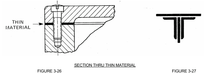
3.9.8.1 Thin Sections. Sections of sheet metal, packing, gaskets, etc., which are too thin for section lining, may be shown solid. See FIGURE 3-26. Where two or more thicknesses are shown, space conducive to microfilming should be left between them. See FIGURE 3-27.
3.9.8.2 Unlined Sections. Shafts, nuts, bolts, rods, rivets, keys, pins, and similar parts, whose axes lie in the cutting plane, are typically not cross-sectioned. See FIGURE 3-28.
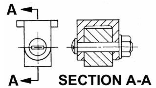
Unlined Sections
Figure 3-28
3.9.8.3 Sections Through Ribs, Webs, Etc. When the cutting plane passes through a rib, web, or similar element, section lines may be omitted from these parts. An acceptable alternate method of representation is to portray the line of intersection of the element (rib, web, etc.) with a hidden line. In cross sectioning the element, every other section line is omitted to accent the division of the element and the body of the part. See FIGURE 3-29.
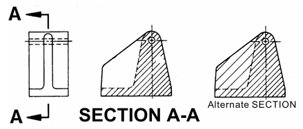
Section Thru Ribs
Figure 3-29
3.9.8.4 Full Sections. A full section is a view which is obtained when the cutting plane extends entirely across the object. See FIGURE 3-30. Cutting plane lines may be omitted if the location of the cutting plane is obvious.

Full Sectional View
Figure 3-30


