3.5 SCALE OF DRAWING.
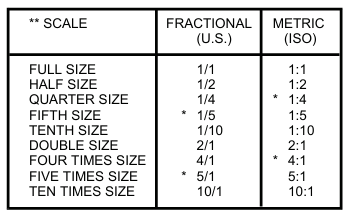
3.5.1 Scale Selection. Wherever possible, drawings should show an object or assembly to full scale, or larger where items or features are too small to see clearly if depicted at full scale. When not practical, drawings may be prepared to a reduced scale. See TABLE 3-1.

* Non-Preferred
** If there is a need for larger or smaller scale than those shown in the Table, it is recommended that the scale be derived by multiplying the whole number by powers of 10. Intermediate scales may be chosen when necessary.
Note: 2D and 3D CAD models should always be modeled at full scale. This excludes CAD files of diagrammatic drawings such as schematics and logic diagrams.
Preferred Drawing Scales
Table 3-1
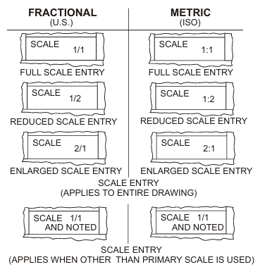
3.5.2 Scale Indication. The primary scale of the overall drawing presentation shall be as a ratio and placed in the Drawing Scale Block located within the Title Block. See FIGURE 3-4.

Scale Entry
Figure 3-4
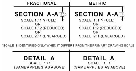
3.5.3 Scale Indication Other Than Primary. Scales that either enlarge or reduce the object from the primary scale used on the drawing shall be identified and entered directly below the DETAIL, VIEW or SECTION extracted from the object. See FIGURE 3-5.

Sectional and Extracted Scale Identification
Figure 3-5
Note: The parenthetic comments shown in FIGURE 3-5 such as “(FULL)” or “(REDUCED)” is not required on the drawing.
3.5.4 Scale of Reproduced Print. The scale of the reproduced original drawing may differ from the original drawing as a result of the techniques, hardware, and software used to reduce or enlarge the drawing.
3.5.5 Change in Dimension. Drawings are drawn to scale within .03 inches. When dimensional changes are made on released drawings, and it is not practical to change the detail to agree with the new dimension, the dimension is underscored with a straight thick line to indicate the out-of-scale condition. See FIGURE 3-6. Care must be taken that if this action is taken on an older drawing, other out-of-scale dimensions shall be changed from the previous wavy line practice to the current straight thick line practice. Where the product definition is on an interactive computer graphics system the scale of the feature and dimension shall be maintained.
Note: This practice primarily applies to manually prepared drawings. Drawings prepared using CAD software and printing equipment (e.g. laser printers) should be more accurate than is described above.

Out-of-Scale Condition
Figure 3-6
3.5.6 Reduced Scale Drawings. Drawings may be made for large parts whose major view may be clearly shown at a smaller scale to reduce the size of the drawing format. These drawings may contain appropriately labeled larger size views or sections of complicated portions if necessary for clarity. See FIGURE 3-5.
3.5.7 Enlarged Scale Drawings. Drawings of exceptionally small parts or views may be drawn to an enlarged scale for clarity. See FIGURE 3-5.
3.5.8 No Scale Drawings. Certain drawings or figures, such as wiring and schematic diagram drawings cannot be drawn to a specific scale. On such drawings, the scale block shall read "NONE".


