3.4 GENERAL PRINCIPLES OF PRESENTATION.
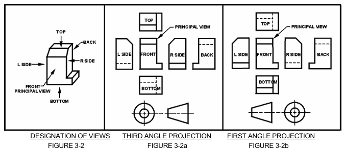
3.4.1 Orthographic Projection. Orthographic projection methods shall be applied to technical engineering drawings for the purpose of uniformity. All example drawings and figures portrayed in this manual will be presented using the "third angle projection method". This policy is generally adopted in the U.S. while the "first angle projection method" is used internationally (ISO).
3.4.2 Method of Identifying the Relative Position of Drawing Views. To clarify any confusion regarding the arrangement of views (this manual shows both inch [U.S.] and metric [international] treatments), the following symbols will be added to drawings as necessary to verify the angle projection method that is portrayed. See FIGURE 3-1.

Angle Projection Method
Figure 3-1
3.4.3 Third Angle Projection Method. This method is preferred and used in the U.S. See FIGURE 3-2a. For interpretation of this method See FIGURE 3-2.
3.4.4 First Angle Projection Method. Countries using international (ISO) standards prefer this method. See FIGURE 3-2b. For interpretation of this method See FIGURE 3-2.
3.4.5 Use of Projection Symbol. The appearance of the third angle projection symbol in the vicinity of the title block as described in Section M4 is as follows:
- U.S. drawings using inch dimensioning - Not required.
- U.S. drawings using metric dimensioning - Mandatory use.
- INTERNATIONAL (ISO users) using metric dimensioning - Not required.

3.4.6 Microfilming Requirements for Drawings in Accordance with MIL-M-9868, Excluding Layouts. Major drawing defects resulting in rejected microfilm are: numbers or characters too light, not clear, or illegible, discontinuous or light lines, and foreign material or markings in drawing area. Adherence to the following guidelines will assist in keeping microfilm rejections to a minimum. MIL-M-9868 is inactive for new application after 1/6/95: Use JEDMICS. See PARAGRAPH 3.4.7.
3.4.6.1 New Drawings. Drawing lines and lettering shall meet the legibility and reproducibility requirements of MIL-PRF-5480 and shall be in accordance with ASME Y14.2M and the following:
- Do not show unnecessary views.
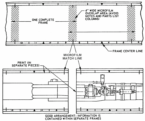
- When possible, place views, sections and Parts List columns between the micro film match lines. See FIGURE 3-3.
- Use standard size drawing formats (See SECTION 6) with microfilm arrow marks.
- Lines and characters shall have even density in accordance with ASME Y14.2M.
- Avoid use of parentheses in notes, field call outs or parts lists.
- Drawings made with photographs will not meet microfilm requirements and must not specifically authorized by contract.
- Decimal points must be uniform, dense and large enough to be of microfilm quality.
3.4.6.2 Revised Drawings. Same as for "new drawings" plus the following:
- Letters, numbers, and line weights shall be consistent with the original drawing preparation.
- Conform to original style of lettering.
Note: The bullet letters missing the sequence above have been moved to Non-Mandatory Appendix A at the end of the DRM. See PARAGRAPH 3.4.6.1 in Appendix A for-drawing rules specific to manually prepared (non-CAD) drawings.

Placing of Views Between Microfilm Match Lines
Figure 3-3
3.4.6.3 Computer-Aided Design (CAD) Drawings. The use of digital data files in preparing drawings is acceptable provided:
- Line conventions and letters may vary for digital data file prepared drawings provided that applicable legibility requirements are met.
- Drawing maintenance requirements and the requirements of this Drawing Requirements Manual (DRM) can be met.
- Microfilming requirements per MIL-M-9868 (Inactive for new application after 1/6/95) can be met. Use JEDMICS. See PARAGRAPH 3.4.7.
- Digital data files are prepared in accordance with the Joint Engineering Data Management Information and Control System (JEDMICS) for storing, retrieving, controlling, managing and distributing engineering data in standard digital format throughout DoD and Industry. Engineering data stored, controlled and distributed by JEDMICS supports the following:
- Manufacture, installation, operation and maintenance of equipment.
- Receipt of engineering data from original equipment manufacturers.
- Re-engineering parts to different specifications.
- Preparing bid sets for spare and repair parts acquisition and replenishment.
3.4.7 Digital Data Delivery Per JEDMICS. Digital data is the preferred delivery method for data. If this option is selected either by option or invoked by contract, it is imperative that an electronic format is selected that can be received, stored, retrieved and used by Government and Industry customers. (Ref: MIL-DTL-31000)
3.4.8 Axonometric (Isometric And Pictorial) Views. Isometric, pictorial, and other views are permitted on drawings as required. Such views are easy to create using 3D CAD software. Refer to PARAGRAPHS 26.1.3 and 26.5.5 in SECTION 26 and the remainder of SECTION 26 for more information.


