3.7 TYPES OF LINES
3.7.1 Line Quality. All lines shall be opaque, and each type of line shall have uniform width, using the line characteristics recommended in TABLE 3-3, except on diagrammatic drawings. All lines shall satisfy the requirements for microfilming.
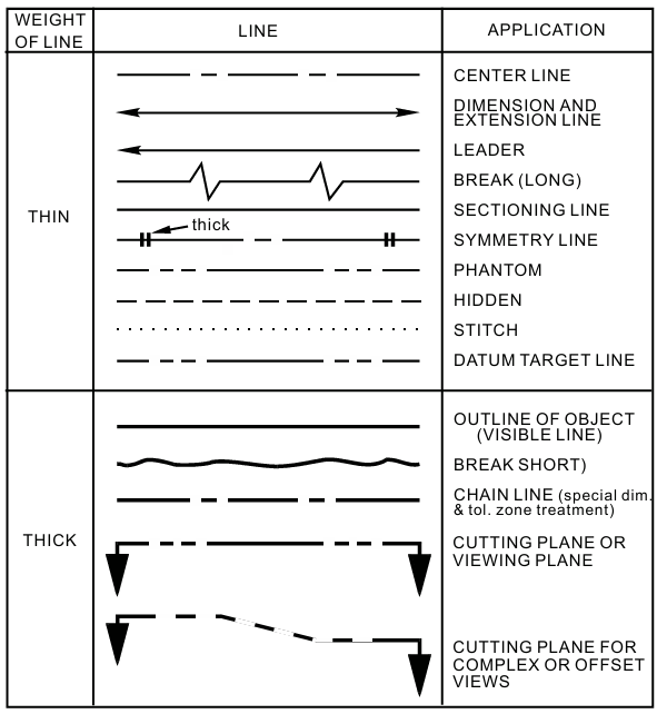
Types of Lines
Table 3-3
3.7.2 Dimension Lines. Dimension lines shall terminate in arrowheads and should be unbroken, except for the insertion of the dimension value and related information. When dimensioning radii, it is permissible to break the dimension line if true center of the radius falls off the drawing into another view or interferes with the logical dimensioning procedure. See TABLE 3-3 and FIGURE 3-8.
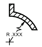
Broken Dimension Line
Figure 3-8
3.7.3 Leader Lines. Leader lines are used to indicate a feature, a part, a portion of a feature, or other annotation to which a dimension, note, or other reference applies. Leader lines are extended at a constant angle. Leader lines are not curved. See FIGURE 3-11. The end of the leader pointing toward the indicated feature shall terminate as follows (See TABLE 3-3 and FIGURE 3-9.)
- A leader that terminates at a line shall terminate in an arrowhead, except as shown in c. below.
- A leader that terminates within the outline of an object shall terminate in a dot.
- A leader that terminates at a dimension line as shown in c. below shall terminate without a dot or arrowhead.

Leader Lines
Figure 3-9
3.7.3.1 Arrowheads. Arrowheads are drawn as shown in FIGURE 3-10.
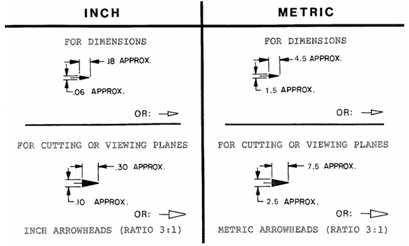
Arrowheads
Figure 3-10
3.7.3.2 Leader Lines Used with Notes. Leaders terminate at the lettering end with a line approximately .125 inch [3.18 millimeter] long, parallel to the lettering of the note and are extended at a constant angle to the part or portion affected by the note.
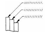
Termination of Leader Lines
Figure 3-11
3.7.3.3 Leader Lines Used with a Circular Area, Shaft, or Hole. The leader line from a dimension and/or local note to a circular area, shaft, or hole shall be directed toward the center of the circle representing the shaft, hole or area, with the arrowhead terminating at the edge of the circle. See FIGURE 3-12.
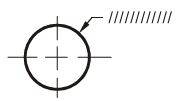
Leader Line Direction
Figure 3-12
3.7.3.4 Leader Lines That Cross Dimension Lines. Leader lines should not cross dimension or other leader extension lines. When it is unavoidable that a leader crosses a dimension line, the leader line or dimension line is not broken at the point of intersection.
3.7.4 Break Lines. Short breaks shall be indicated by solid freeform lines; long breaks shall be indicated by full ruled lines with zig zags. See TABLE 3-3 and FIGURE 3-13.

Break Lines
Figure 3-13
3.7.4.1 Break-Out Methods. Shafts, rods, tubes, etc., which have a portion of their length broken out, shall indicate the ends of the break as in FIGURE 3-14.
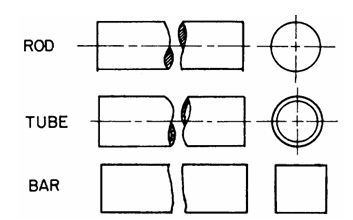
Breaklines
Figure 3-14
3.7.5 Center Lines. Center lines are shown in pertinent views of holes, round shapes on detail drawings, on assembly drawings to indicate the center of features, or to indicate the travel of a center. See TABLE 3-3 and FIGURE 3-15. Center lines may cross without voids. See FIGURE 3-14. Very short center lines may be unbroken if there is no confusion with other lines. (Note: Center lines are not required on annotated models.)
3.7.6 Phantom Lines. Phantom lines are used to indicate an alternate position, repeated detail, or the interfacing position of an absent part. They shall be composed by a series of one long and two short dashes evenly spaced with a long dash at each end. See TABLE 3.3 and FIGURES 3.15, 3.16 and 3.17.
3.7.7 Section Lining. Section lining shall be used to indicate the exposed surface of an object in a cross-sectional view. See TABLE 3-3 and FIGURE 3-15.
3.7.8 Extension Lines. Extension lines shall be used to indicate the extent of a dimension or an extension from a surface. They shall not touch the object outline. See TABLE 3-3 and FIGURE 3-15.
3.7.9 Datum Target Lines. Datum target lines are used to establish datum target lines or the boundary of datum target areas, and consist of one long dash and two short dashes evenly spaced, per TABLE 3-3. See SECTION 5 for the use of datum targets. Datum target lines are the same as Phantom lines.
3.7.10 Hidden Lines. Hidden lines are used to represent features that are not directly visible in a particular view. Hidden lines should be used when required for clarity and shall consist of short evenly spaced dashes. They should begin with a dash in contact with the line from which they start, except when such a dash would form a continuation of a collinear object line. Dashes should touch at corners, and arcs should start with dashes on the tangent points. See TABLE 3-3 and FIGURE 3-15.
3.7.10.1 Hidden Surfaces Intersect. If possible, when two or more hidden surfaces intersect, a dash in one line should cross a dash in the other line.
3.7.11 Cutting Plane and Viewing Lines. When it is necessary to indicate where a section is taken, a cutting plane line is used. Section letters are placed in front of the directional arrowheads, except for alternate viewing plane in which case they are placed in back of directional arrowheads. See TABLE 3-3 and FIGURE 3-15.
3.7.12 Object Lines (Outline Or Visible Outline). Object lines shall be used for all lines on the drawing representing the visible outlines of the object. See TABLE 3-3 and FIGURE 3-15.
3.7.13 Chain Lines. Chain lines are used to indicate a limited length or area receiving additional treatment within limits specified on the drawing. See FIGURE 3-15. Chain lines are also used to indicate a projected tolerance zone. Chain lines consist of appropriate length lines and short dashes. See TABLE 3-3.
3.7.14 Stitch Lines. Stitch lines are used to indicate a sewing or stitching process and are shown as dots approximately .01 inch [0.3mm] in diameter and .01 inch [0.3mm] apart. Short dashes may be used over extended lengths. See TABLE 3-3.
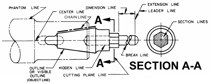
Line Conventions
Figure 3-15
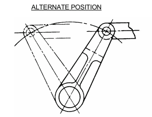
Alternate Position
Figure 3-16
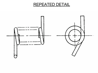
Repeated Detail
Figure 3-17


