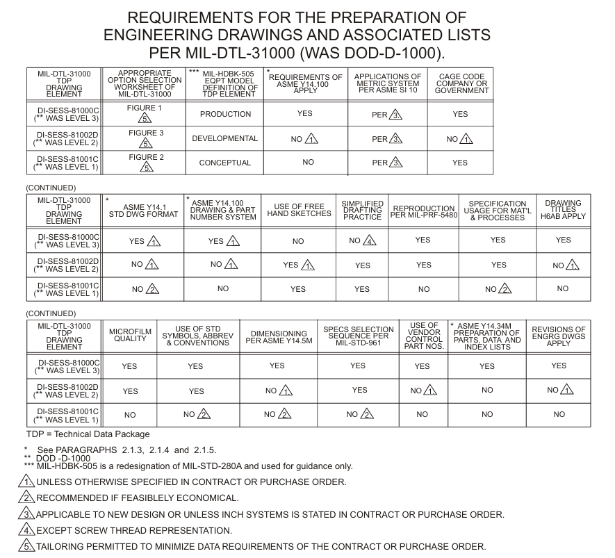
2.4 Drawing and Model Requirements
2.4.1 Drawings and Models Prepared to Data Item Description (DID) Requirements. Engineering drawings and models are prepared to meet the requirements of specifications and standards referenced on Data Item Descriptions (DIDs) as required by the contract or purchase order as cited by Statement of Work (SOW). These drawings and models are normally specified on the Contract Data Requirements List (CDRL) (FORM DD 1423) (See APPENDIX A FIGURE 2A-9) along with the Technical Data Package (TDP) elements for drawings required to provide the necessary design disclosure. Combination of TDP elements may be specified in the contract or purchase order.
2.4.1.1 If TDP Elements Are Not Specified. On a contract where the Technical Data Package (TDP) elements for drawings and models are not specified, or on design activity R&D and commercial work, use the following guide:
- Prepare all work on the design activity standard engineering drawing format.
- Use the design activity’s drawing and part numbering system.
- Company, government and industry association standards or specifications may be omitted for parts, processes and materials, but their use is encouraged when economically feasible.
- Use of standard parts is recommended.
- Freehand sketching is permissible, and drawings need not be to an exact scale.
- Drawings must be legible and reproducible.
- Use of drafting standards for symbols and conventions is recommended.
- Use of simplified drafting techniques is encouraged.
- Drawings must contain sufficient information necessary for fabrication, installation, assembly, procurement and inspection.
- 3D solid models and drawings based on 3D solid models should conform to SECTION 26 and paragraph 26.34 and sub-paragraphs in particular.
2.4.1.2 When TDP Elements Are Specified. If a contract specifies Technical Data Package (TDP) elements for engineering drawings, models, or associated lists, these elements shall be prepared to the disclosure level designated. When preparing an engineering drawing, model, or associated list, the contract or purchase order should list the following requirements of TDP element as listed:
- Conceptual Design Drawings/Models and Associated Lists per paragraph 2.3.41.1.
- Developmental Design Drawings/Models and Associated Lists per paragraph 2.3.41.2.
- Product Drawings/Models and Associated Lists per paragraph 2.3.41.3.
Use the following guide for TABLE 2-1.
- Whether a Government Design Activity or Contractor Design Activity designation and identity as assigned by Commercial And Government Entity (CAGE) 5-digit code is to be placed in the Title Block of the engineering drawing or associated list.
- Whether a Government Design Activity or Contractor Design Activity drawing numbers will be assigned.
- If Government Design Activity drawing numbers are to be assigned, identify the assigning activity. If Government drawing formats are to be supplied, identify the source.
- Whether the mono-detail or multi-detail drawing system will be used.
- Which kinds of associated lists are required.
- Assembly level at which associated lists will be prepared.
- Whether associated lists shall be integral with, or separate from, the engineering drawing.
- Which drawing format, type, class and quality of stock are required.

Table 2-1
2.4.1.3 Existing Engineering Drawings/Models and Associated Lists. Engineering drawings, models and associated lists prepared prior to the above requirement of PARAGRAPH 2.4.1.2 are acceptable if the engineering drawings, models and associated lists have been previously accepted by the Government, or if they meet the following requirements:
- They are acceptable for entry into the government's repository system. (i.e. are identified by name and address of design activity, Commercial and Government Entity (CAGE) code, drawing nomenclature, drawing (part) number, in accordance with MIL-STD-100, and contract number).
- The format, legibility requirements, drawing practices, modeling practices, and symbols used (including the use of legends/explanations for nonstandard symbols) are such that their intent and interpretation of all requirements are clear and unambiguous.
- They provide the necessary design disclosure information for the drawing or model TDP element for which they are furnished.


